A graphics engine written from scratch in rust that can load .obj/.mtl files.
Building a graphics engine from scratch (WIP)
Introduction
This blog post is my attempt to break down some of the fundamental concepts behind computer graphics with diving too deeply into the math. I’ll try to explain in a way that someone with minimal experience can still follow and (hopefully) find enjoyable.
Quick side note: the engine I wrote runs entirely on the CPU. I avoided shaders on purpose—not because I didn’t want performance, but because I wanted to learn what’s actually going on under the hood. Sure, it’s slower (especially on larger meshes), but the trade-off was worth it for the learning experience.
This is also my first project ever in rust so excuse the possible bad rust practices.
Important Concepts
The following few sections explain some foundational concepts that readers may find confusing in later sections. These concepts will serve as primitives that are taken for granted later on.
Homogeneous Coordinates
When you think of rendering something in 3D, you’d probably imagine the standard cartesian coordinate system:
But when working with graphics it’s often more practical to use homogenous coordinates:
The extra value, w may seem confusing, but it plays an important role in how objects show up on the screen.
To understand what this value actually means, lets simplify and zoom into two dimensional homogenous coordinates:
Imagine a projector casting a 2D image onto a wall. As the projector moves closer to the wall, the image shrinks. Move it farther away, and the image appears larger. Even though the image itself is flat and 2D, its appearance depends on a third factor: the distance from the wall. We can represent this variable as w.
So in 2D homogeneous coordinates, w acts like a scale factor. It determines how big or small the projected points should appear once transformed into screen space.
Now, scale that concept up to 3D. It’s a bit trickier to visualize, but the idea is the same. That w value lets us handle things like perspective projection and affine transformations more elegantly. In fact, most of the time, we will convert back to cartesian coordinates with something called a perspective divide which i’ll cover later on.
TL;DR: Homogeneous coordinates contain an extra variable
wwhich helps with matrix math and makes perspective projection possible.
Barycentric Coordinates
In graphics, we usually break everything down into triangles. Why triangles? Because they’re the simplest possible polygon. You can’t make a shape with fewer points—and better yet, you can construct pretty much any complex surface by combining a bunch of them. So we can solve all our rendering problems through triangles, and decompose larger shapes into more triangles.

Once we’re working with triangles, one of the fundamental problems we have to solve is this:
Given a point, how do we know if it lies inside a triangle or not?
That’s where barycentric coordinates come in.
Say we have a triangle composed of three verticies $(A, B, C)$ and a point $P$.
By connecting $P$ with each of $A$, $B$, $C$, we create three smaller triangles.
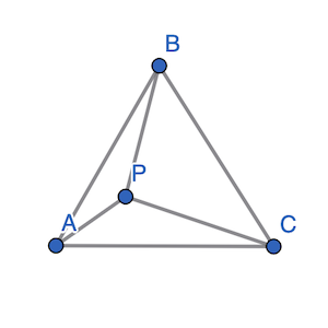
If $P$ is inside of $(A, B, C)$ you’ll notice that the sum of the areas of these three sub-triangles is exactly equal to the area of the original triangle.
However, if $P$ is outside of $(A, B, C)$:
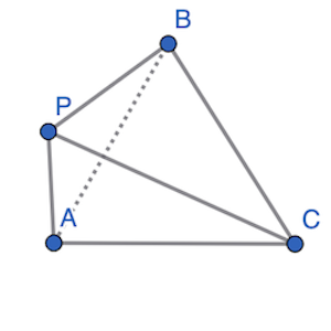
We notice the sum of the areas of the three sub-triangles is greater than the area of $(A, B, C)$.
Lets call area of the three subtriangles $T1$, $T2$ and $T3$. If $P$ lies inside $(A, B, C)$:
Say $\alpha$, $\beta$ and $\gamma$ are the three components of this sum:
Then,
So every point relative to this triangle will have its own unique $\alpha$, $\beta$ and $\gamma$. If $\alpha$, $\beta$ and $\gamma$ are all less than 1 (because they are ratios of the sub-triangle to the area of the triangle) and greater than 0, we know the point is inside the triangle.
We call $\alpha$, $\beta$ and $\gamma$ the barycentric coordinates of the point $P$ relative to triangle $(A, B, C)$.
This simple concept becomes incredibly powerful when we want to interpolate values across the surface of a triangle—like color, texture coordinates, normals, or even depth. Barycentric coordinates help us “blend” data smoothly across a surface.
TL;DR: Every point $P$ relative to a triangle can be expressed using barycentric coordinates $\alpha, \beta, \gamma$. If all three are between 0 and 1 and $\alpha + \beta + \gamma = 1$, then the point lies inside the triangle; otherwise, it’s outside. Since these values vary across the triangle, they’re super useful for interpolating things like color, position, or texture later on.
The Graphics Pipeline
This section will give a broad overview of the journey data takes through the graphics pipeline and eventually gets displayed on a screen.
Building a mesh
In the world of 3D graphics, before you can render (i.e., visually display) anything on screen, you first need to define the shape or object you want to render.
A Mesh is essentially a blueprint for a 3D object. It’s made up of:
Vertices: Points in 3D space.

Triangles: Groups of three vertices that form the faces of the object.

Materials (covered later): Information about how the surface of the mesh should look—color, texture, shininess, etc.
Most modern 3D engines (like Unity, Unreal, or even WebGL) follow this same standard structure.
The following is an example of a simple quadrilateral mesh made up of two triangles.
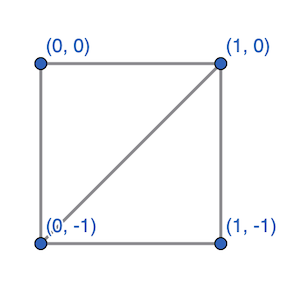
Here we could define the following labeled verticies:
Then our list of triangles could look like:
Something important to keep in mind is the winding order of your triangles. That is, the order in which you list the vertices (either clockwise or counterclockwise). This order must stay consistent across every face in the mesh.
Why does this matter? Because the winding order is used to calculate the normal vector, which is the direction pointing straight out from the surface of the triangle. It helps define which side is the “front” of the face. If the winding isn’t consistent, some normals might point outward while others point inward, which can cause all kinds of rendering issues like weird lighting or backface culling glitches.
Here is the line where I load meshes from .obj and .mtl files. I wrote the parser for these files from scratch in loader.rs but the main takeaway is that this returns a list of verticies, triangles and materials that make up my mesh.
The model matrix
Once we’ve got a basic idea of what to render, the next step is to actually do something with our mesh. That means we can translate it, rotate it, and scale it all using matricies.
Now, if you’re not super familiar with matrices, just think of them as a neat way to apply transformations (like moving or rotating) to points in 3D space.
For example rotating some homogeneous vector $(x, y, z, w)$ by $\theta$ degrees around the y-axis can just be represented by the following matrix multiplication.
Don’t worry if you dont understand the math here. The result is just a new 4x1 vector that gives you the rotated coordinates.
Now, did you notice that the rotation matrix is 4x4 instead of the usual 3x3? That’s because we’re using homogeneous coordinates, which include that extra w component. This lets us pack translation, rotation, and scaling into a single matrix.
So instead of applying transformations one by one, we can combine them into one matrix and apply it all at once. Super efficient—and it keeps things clean and manageable when rendering 3D scenes.
Here is the portion of my code where I apply a simple translation matrix onto my mesh.
The view matrix
So, we’ve created a mesh and applied whatever transformations we needed. Now comes the next step in the graphics pipeline: setting up the camera.
Up until this point, everything has been in what’s often called model space. That just means the mesh exists in its own local coordinate system. You can think of it like its own little world. But now we need to shift that into something more useful: view space.
Remember, matrices represent transformations. The view matrix is no different. Its job is to take everything from model space and transform it into view space which is basically the scene as the camera would see it.
When creating a view matrix we have a few properties of the camera to consider:
Where the camera is
Where the camera looks at.
Which direction should be up.
That last one might seem a little strange at first. Why would we need to tell the camera what up is?
Well, think about it like this: if you only give the camera a position and a target, there are still countless ways it could orient itself and still be pointing at the target. It could be upright, tilted, or even upside down. The up vector removes that ambiguity. It locks in the roll of the camera so that the world isn’t accidentally rendered sideways or flipped.
From these three parameters, we need to compute an orthogonal basis, or just three perpendicular vectors which can serve as the basis for transformation into the camera’s view.
The following section contains a snippet of code deriving the view matrix so feel free to skip it if you just want the general idea of how things work. I used rusts nalgebra library’s built in look_at_rh function to generate it in my code.
/// Creates a right-handed look-at view matrix
pub fn look_at(eye: Point3<f32>, target: Point3<f32>, up: Vector3<f32>) -> Matrix4<f32> {
    let forward = (target - eye).normalize();
    let right = up.cross(&forward).normalize();
    let up = forward.cross(&right);

    let rotation = Matrix4::new(
        right.x,    up.x,    -forward.x,    0.0,
        right.y,    up.y,    -forward.y,    0.0,
        right.z,    up.z,    -forward.z,    0.0,
        0.0,        0.0,     0.0,           1.0,
    );

    let translation = Matrix4::new_translation(&-eye.coords);
    rotation * translation
}
So just to review our graphics pipeline so far. Given vertex $p$, model matrix $M$, and view matrix $V$:
Here is an example of the view matrix in my code. I implemented mouse controls and wasd movement so there are some key handling functions that simply just update the camera’s position and target.
If you aren’t following the exact math, thats okay! Just know the $view$ value from above is the point $p$ transformed by some matrix, and then transformed into the camera’s point of view.
The projection matrix
Once we’ve got our mesh transformed to the point of view of our camera, the next step is to project those verticies onto a 2D screen. Really all the projection matrix does is find a way to squeeze our 3D coordinates onto a 2D space. We call this projecting the mesh onto the screen.
Loading .obj and .mtl files
Texture Mapping
Lighting and Shading
Optimization
Check out the source